Table of Contents
When discussing battery performance, capacity, voltage, or cycle life often take center stage — while an equally important parameter is easily overlooked: internal resistance. In fact, it plays a decisive role in dynamic performance, efficiency, and long-term reliability. This article explains the physical nature of internal resistance, its crucial role in performance and service life, and the key factors behind its changes — helping you gain a comprehensive understanding of this quality-defining parameter.
1. What Is Battery Internal Resistance?
Internal resistance describes the resistance a battery opposes to current flow during operation. When current flows through electrodes, electrolyte, and conductors during discharge, various resistances arise — resulting in voltage drop, energy loss, and heat generation.
Ohmic internal resistance: Caused by the conductivity of conductors, electrodes, tabs, electrolyte, and separator — mainly determined by material properties.
Electrochemical polarization resistance: Results from finite reaction speeds at the electrode–electrolyte interface; electrode potentials deviate from equilibrium under load, driven by reaction kinetics.
Concentration polarization resistance: Caused by concentration gradients between the electrode surface and the bulk electrolyte; under high currents, ion diffusion becomes the limiting factor.
In practice, an equivalent value is often determined using an AC method, known as AC internal resistance, which summarizes all partial resistances. The basic rule is: Uload = UOCV − I × Rin. The higher the internal resistance, the greater the voltage drop and the lower the usable output power.
2. How Does Internal Resistance Develop?
The causes are diverse and are shaped by material properties, manufacturing processes, and aging mechanisms:
Conductivity of active materials: Low electronic conductivity increases the resistance path.
Contact between collectors and electrodes: Poor contact increases contact resistance.
Electrolyte concentration & conductivity: Too low a concentration or aged electrolyte slows down ion transport.
Separator impedance: Low porosity or impurities hinder ion flow.
Welding and connection quality: Poor welds, loose screws, and oxidation cause locally high resistance.
As usage time increases, internal resistance and degradation rise due to material aging, active material detachment, and thickening of the SEI layer. The increase in internal resistance is one of the main drivers of performance decline.
3. Impact on Performance & Efficiency
Internal resistance directly determines performance under high load:
Voltage drop: Under load, terminal voltage falls below the rated value; the higher the current, the greater the drop.
Lower output power: P = U × I; when U decreases due to Rin, available power is reduced.
Lower energy efficiency: Part of the energy is converted into heat instead of being delivered as usable power.
Temperature rise: I2R losses heat the cells; insufficient cooling accelerates aging and may even create safety risks.
Practical example: Two batteries with the same capacity — the one with lower internal resistance maintains voltage more stably during motor start-up or inverter start-up, delivers more power, and heats up less.
4. Internal Resistance & Service Life
Internal resistance serves as an important aging indicator. As cycle count increases, it rises for several reasons:
SEI layer evolution: In lithium-ion batteries, the SEI on the anode continues to grow, increasing Li-ion transfer resistance — a key reason for the rise in Rin.
Electrolyte decomposition & loss: Side reactions consume active lithium and change composition and conductivity.
Structural degradation of electrodes: Detachment, phase transformations, dissolution, and collector corrosion lengthen electron/ion pathways.
Contact resistance at interfaces: Mechanical stress and volume changes increase contact resistance between electrode and collector.
When Rin rises, usable power decreases even before noticeable capacity loss occurs — the “practically usable” capacity shrinks due to stronger voltage drops. In the long term, high Rin can lead to hotspots, thermal fatigue, or housing deformation.
Definition of end of life: Industry standards often define end of life when Rin reaches 1.5 to 2.0 times its initial value. The increase in Rin often precedes capacity degradation and limits power delivery. A cell with 80 % remaining capacity may already fail under load in a device if Rin has doubled.
Conclusion: Low internal resistance means not only high performance, but also longer cycle life.
5. Key Factors Affecting Internal Resistance
Rin is dynamic and changes with environment and usage:
Temperature: In cold conditions, electrolyte viscosity increases and ion mobility decreases — Rin rises sharply. High temperatures accelerate side reactions and permanently increase Rin.
State of charge (SOC): At low SOC, Rin is significantly higher.
Discharge rate & cycle count: High C-rates increase mechanical stress and side reactions, causing Rin to grow faster; Rin increases monotonically with cycles.
Storage duration: Even at rest, side reactions continue; long storage increases SEI thickness and changes the electrolyte, causing Rin to rise.
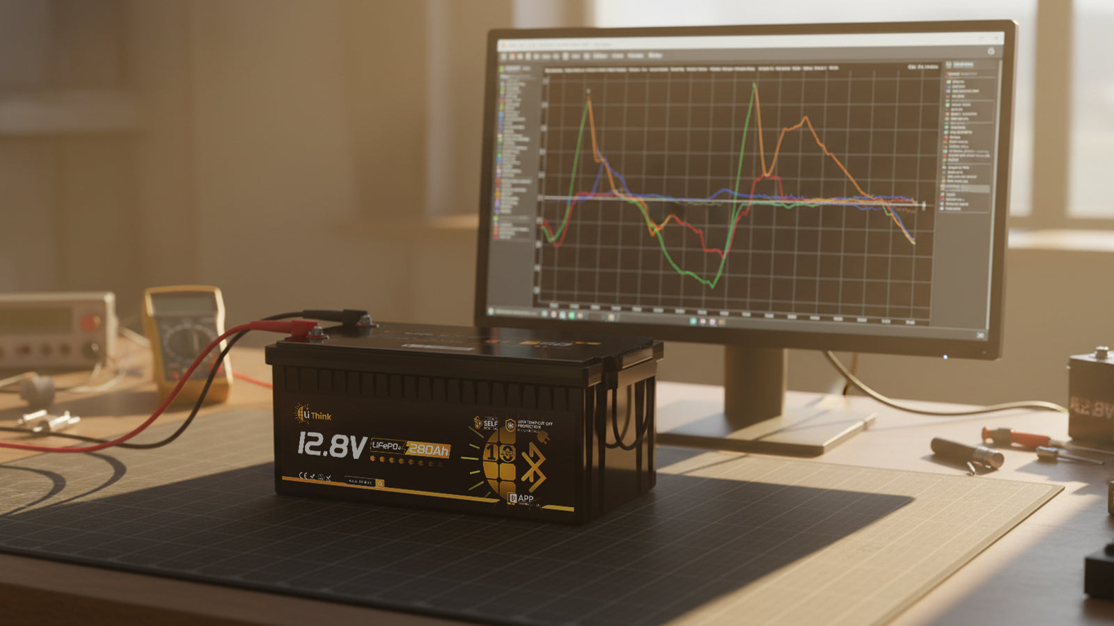
Lithink LiFePO₄ uses multi-point temperature sensing and active balancing to monitor these variables and keep Rin stable across different environments.
6. How to Measure Internal Resistance?
Accurate measurement is essential for performance evaluation, SOH monitoring, and pack matching. Common methods include:
Short-duration DC load test (DCIR): Apply a brief high-current pulse, measure the voltage drop, and calculate Rin; simple, but strongly dependent on temperature and SOC.
AC internal resistance (ACIR): Milliohm measurement using an AC signal; more accurate, but requires a measuring instrument.
Electrochemical impedance spectroscopy (EIS): Separates ohmic, charge-transfer, and diffusion components — the standard method in laboratory and development environments.
For practical use, measurement at room temperature and 50–70 % SOC is recommended to obtain reproducible reference values.
7. Lithink: Low-IR Design Philosophy
Lithink regards “low internal resistance” as a core objective in performance design. Our solutions:
A+ automotive cells: Cell Rin ≤ 1 mΩ, excellent cycle consistency.
Dual current-collection structure: Copper-alloy busbars minimize path impedance.
Multi-point temperature monitoring: Three sensors detect heat rise; the BMS dynamically limits current.
Intelligent BMS: Automatic balancing, short-circuit/overcurrent protection, and low-temperature heating control ensure long-term stability.
Fully encapsulated, vibration-resistant structure: Six-sided epoxy insulation + alloy frame prevent contact-related Rin increases caused by vibration.
This allows Lithink batteries to maintain stable voltage even under high loads — such as RV air conditioners, inverter start-up, or trolling motors — while generating less heat and combining high power output with long service life.
Conclusion
Internal resistance accompanies the entire battery life cycle, from research and production to application. It determines instantaneous power and energy efficiency — and reflects both the chemical and structural health of a battery. Understanding and controlling internal resistance means more power, longer service life, and higher safety.
Share:
How to Store LiFePO4 Batteries and Prevent Capacity Loss