Table of Contents
- Introduction: Voltage Drop When Starting the Inverter
- 1. Inverter Start-Up Moment and Steady-State Operation
- 2. Direct Cause: Transient Voltage Drop
- 3. BMS Protection Mechanism During Start-Up Voltage Drop
- 4. Why 12V Lithium Batteries React Differently
- 5. Why More Capacity Does Not Automatically Solve the Problem
- 6. Solutions for Voltage Drop During Start-Up
- 7. Conclusion
A voltage drop when switching on the inverter is one of the most common and frequently misinterpreted issues in real-world use with lithium batteries. Many users quickly attribute this phenomenon to statements such as “the battery is too weak”, “the voltage is not sufficient”, or “the power cannot be supplied”. From a technical perspective, however, this explanation is not precise.
The voltage drop during inverter start-up is not a problem caused by an incorrect voltage parameter, but the result of the interaction between transient power supply capability and system impedance. Anyone who truly wants to understand and solve this problem must consider the inverter’s start-up characteristics, the battery’s transient discharge capability, and the electrical properties of the entire DC side together.
1. Inverter Start-Up Moment and Steady-State Operation
Before discussing voltage drop, one basic fact must first be clear: the start-up moment of an inverter and its stable operation at rated power are two completely different operating states.
1.1 Current Characteristics During Start-Up
When the inverter is switched on, several processes must take place at the same time:
- Rapid charging of the internal capacitors
- Switching of the power semiconductors
- Building up a stable AC output voltage
During this process, a very high inrush current occurs briefly on the DC input side.
This current is usually 2 to 5 times higher than the inverter’s steady-state operating current and may be even higher under certain load conditions.
Characteristic 1: The duration of the inrush current is very short.
Characteristic 2: The requirements for the transient performance of the power supply system are extremely high.
That is exactly why an inverter that can operate without problems in steady-state conditions may still cause a voltage drop or protection shutdown during the start-up moment.
2. Direct Cause: Transient Voltage Drop
The voltage drop during the inverter’s start-up moment is not a random phenomenon, but can be clearly explained using the fundamentals of electrical engineering.
2.1 Mechanism Behind Transient Voltage Drop
During the inverter’s start-up moment, the battery voltage can be simplified as follows:
Terminal voltage = battery open-circuit voltage – start-up current × total system impedance
The total system impedance includes not only the battery itself, but consists of several parts:
- The internal resistance of the battery
- The on-resistance inside the BMS
- The resistance of the connecting cables
- The contact resistance of terminals, fuses, and connectors
When the inrush current rises suddenly, even seemingly very small resistances can cause a clearly measurable voltage drop during this brief moment.
2.2 Why No Problem Is Often Visible at No Load or Under Light Load
At no load or under light load:
- The current is very small.
- The voltage drop is practically negligible.
In this state, different batteries and different systems behave very similarly at the terminals. However, this is exactly what hides the real performance differences of the system under extreme conditions.
3. BMS Protection Mechanism During Start-Up Voltage Drop
When discussing voltage drop during inverter start-up, the BMS is often mistakenly seen as the cause. However, this view is not correct.
3.1 The Nature of the BMS
The main task of a BMS is safety control, not performance optimization. It essentially evaluates only two things:
- Whether the current exceeds the safe limit
- Whether the voltage falls below the safe threshold
As soon as one of these conditions is met, the BMS follows its protection logic and limits current or shuts down the output.
3.2 Typical Trigger Path During Start-Up
During the inverter start-up process, the trigger sequence often occurs as follows in practice:
- The inrush current rises sharply within a very short time.
- The total system impedance causes a momentary voltage drop at the terminal.
- The terminal voltage falls below the undervoltage threshold set in the BMS.
- The BMS detects an abnormal condition and disconnects the output.
From the user’s perspective, this appears as a sudden battery shutdown. From a technical perspective, however, the BMS is simply carrying out the correct protection function according to its safety logic.
4. Why 12V Lithium Batteries React Differently
The differences between various 12V lithium batteries become especially clear during inverter start-up. The reason is not the nominal voltage, but several decisive technical factors.
4.1 Differences in Internal Resistance
The lower the internal resistance of the battery, the smaller the voltage drop at the same inrush current. Internal resistance is influenced by several factors:
- Cell material and manufacturing process
- Cell capacity and cell size
- Series/parallel design and internal connection structures
Under highly dynamic discharge conditions, this difference is directly reflected in voltage stability at the terminals.
4.2 Differences in BMS Parameters
The settings of different BMS systems are not identical. Differences may include, for example:
- The trigger point of the undervoltage protection function
- The threshold of overcurrent protection
- The permitted duration of inrush current peaks
Even if two batteries have similar cell performance, their start-up behavior can differ significantly due solely to different BMS strategies.
4.3 Amplifying Effect of System Connection Impedance
Under transient high-current conditions, the influence of the connection path must not be underestimated. The following factors increase total impedance:
- Cables that are too long
- Cable cross-section that is too small
- Asymmetrical wiring
These factors further increase the voltage drop during start-up.
5. Why More Capacity Does Not Automatically Solve the Problem
A common misconception is: if you simply use a battery with a larger capacity, the voltage drop during inverter start-up will disappear. From a technical perspective, this assumption is only partially correct.
5.1 Relationship Between Capacity and Transient Power Capability
Battery capacity in Ah primarily describes:
- How long the battery can deliver energy at a lower C-rate
The inverter start-up problem, however, concerns something different:
- Whether a sufficiently high transient current can be delivered within a very short time
- Whether the terminal voltage remains above the protection threshold while doing so
These two aspects do not have a simple one-to-one relationship.
5.2 Limits of a Pure Capacity Upgrade
If only the capacity is increased without also changing the following:
- The cell structure
- The internal resistance level
- The BMS protection strategy
then the transient behavior of the system during start-up often does not fundamentally improve.
6. Solutions for Voltage Drop During Start-Up
Truly effective solutions must always start at the system level, not just at a single component.
6.1 Reduce the Total Impedance of the System
This is the most direct and fundamental measure. It includes:
- Using shorter and thicker DC cables
- Designing positive and negative cable routing symmetrically
- Reducing unnecessary transitions, connectors, and connection points
Under transient high-current conditions, these improvements are often more effective than simply replacing the battery.
6.2 Match the Inverter and Battery in Terms of Start-Up Characteristics
Already during the selection phase, attention should be paid not only to the inverter’s rated power, but above all to:
- The characteristics of the inrush current
- The allowable input voltage sag during start-up
The degree of matching between inverter and battery directly determines the stability of the system during the start-up moment.
6.3 Choose Battery Designs with Higher Transient Discharge Capability
In practice, the decisive factors are primarily:
- Transient discharge capability
- The level of internal resistance control
- The BMS strategy for handling inrush current peaks
These factors are often much more important than simply looking at Ah capacity or rated discharge current.
Important selection focus: For inverter start-up, compressor loads, and mixed loads, you should primarily consider the battery’s current peak resistance across different time windows — not just the rated discharge current.
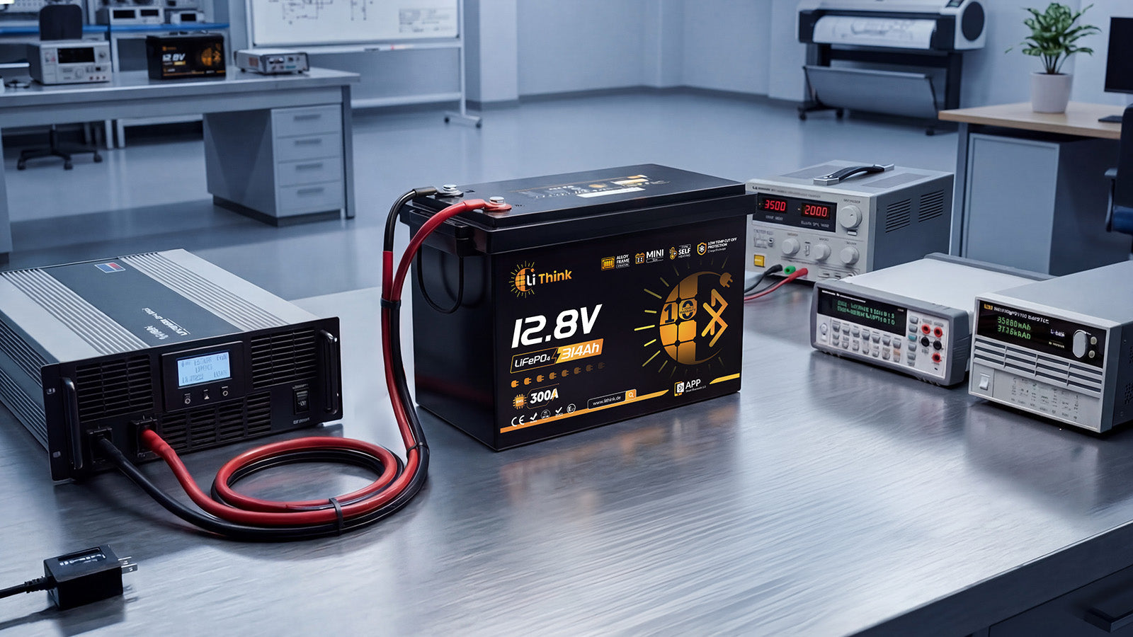
Example Lithink 12V 334Ah: The surge current capability is 1000 A/1 s, 700 A/3 s, 500 A/5 s, and 300 A/10 s.
Typical application scenarios: These performance figures are intended to cover peak currents when starting air-conditioning compressors, switching on mixed loads, or starting water pumps, thereby reducing the likelihood that protection will be triggered due to voltage drop.
7. Conclusion
At its core, voltage drop during inverter start-up is a phenomenon in which the system cannot provide the required transient current within an extremely short time, causing the voltage to drop. The result is jointly determined by the inrush current, the total impedance of the DC side, and the undervoltage and overcurrent protection thresholds of the BMS.
The effective solution is therefore systematic matching and optimization of the entire system: the total impedance of the DC side must be reduced, the start-up characteristics of the inverter must be properly matched with the battery’s transient discharge capability, and the BMS protection response must be correctly understood within safe limits.
Share:
Monitor Lithink Bluetooth LiFePO4 Batteries in Home Assistant
Common RV Battery System Configuration Mistakes